DC Motor with Encoder
DC Motor
A DC Motor equipped with a built-in encoder is going to immensely help us in precisely controlling the speed at which the motor rotates. Let us go through the basics behind such an encoder and how it relates to the speed ot the motor.
In this tutorial, we will look at how to do speed control using a DC Motor that has a quadrature shaft encoder. I will be using this DC Motor with Encoder as a reference. The main reason being that it has a very good specification documentation. The instructions here will be the same for any similiar motor with a quadrature encoder attached to the shaft of the motor.
I will refuse to talk about DC Motors in general as that is not the focus for us, but rather to understand how to make use of the Encoder pulses with which we could measure the RPM and thus control the speed.
Understanding DC Motor with Encoder
So we need to now effectively understand a little about the DC Motor and the need for an Encoder unit. A one liner - a DC Motor is a mechanical device that converts basically electrical energy to mechanical energy. Ok that's simple enough but that's enough. Why do we need an Encoder? With the target that we are trying to build, we need to be able to more precisely control the speed and direction of the motor which effectively translates to the navigability of the Navo. Encoders transform mechanical motion into electrical pulses that can then be used by a controller unit (like the Arduino) to make adjustments and fine tune the motor speed and direction.
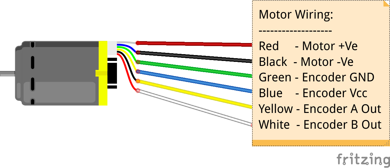
As mentioned before, we will use DC Motor with Encoder. The table and the image below clarifies the wiring definitions.
| Color | Function |
|---|---|
| Red | motor power (connects to one motor terminal) |
| Black | motor power (connects to the other motor terminal) |
| Green | encoder GND |
| Blue | encoder Vcc (3.5 V to 20 V) |
| Yellow | encoder A output |
| White | encoder B output |
There are different types of encoders available, such as liner encoder or rotary encoders. A DC Motor encoder basically has a rotary encoder which is often times mounted to the shaft of the motor. The rotary encoder used here is a 6 pole magnetic disc attached to the shaft of the motor, along with two Hall effect sensors. When the motor turns, the 6 pole magnetic disk rotates past the two sensors and when each time a magnetic pole passes one of the sensor, the encoder outputs a digital pulse. So here with the two hall effect sensors, we get two output signals separated by 90 dgrees. The sketch below shows the basic working principle behind a Rotary magnetic encoder.
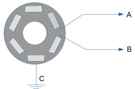
It can be seen that the two sensing units (marked A & B) will emit a pulse signal as soon as they hit the underlying magnetic pin (6 of them as can be seen in the diagram above) and this pulse signal can be translated / understood in terms of the direction and speed of the motor. I will not explain more about this topic, but here is a very descriptive video on understanding DC Motor encoders in much detail.
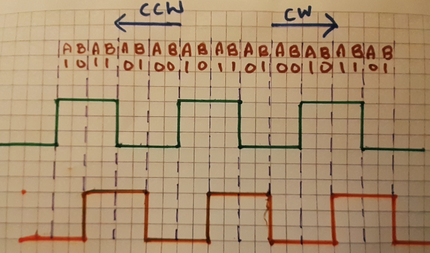
CW -> Clockwise Direction CCW -> Counter-Clockwise Direction
we can now infer from the square wave pulse signals that binary combinations for the pulses A & B, we can infer that when we get a pulse signal that has a RISING for the pulse A and during this if we measure a LOW for pulse B, we know that the motor is in the forward direction (CW). If on the other hand when the pulse signal for A has a RISING and during this if we measure a HIGH for pulse B, we know that the motor is in the reverse direction (CCW).
Ok that's for the direction. Now let us see how we could leverage this information and with some additional data from the Motor's specification, determine the RPM which forms the basis for doing speed control. To do this we need to understand the motor's specification.
The DC Motor that we use has a metal gearbox with a ratio of 20.4:1 and a shaft with a diameter of 25 mm. The resolution of the encoder that is assembled to the motor shaft is rated at 48 Cycles Per Revolution (CPR). What this exactly means is that if the motor shaft turns one round the output of the encoder counts up to 48. It is important to notice that the gearbox shaft is different from the motor shaft and as mentioned before, the ratio of rotation between these shafts is 20.4:1. So if motor shaft turns 20.4 times, gearbox shaft turns just 1 time. So with this understanding, the cycles per revolution or pulses per revolution of the gearbox shaft can be calculated with the following formula:

So with this formula at hand, we get the gearbox CPR = 20.4 * 48 = 979.62
The gearbox output resolution (979.62 CPR) is the only value that we will get from DC motor as feedback which when coupled with time helps us do speed control. Now the formula to calculate the RPM (speed) is given by:

where revolutions per count or revolutions per pulse equates to 1 / 979.62 (we know that pulse per revolution PPR or CPR is 979.62), so if we plug in these values into the equation above, we end up with the following:

We then have to plug in this equation into the sketch below and measure the number of pulse counts every second. Let us see how the sketch looks like!
DC Motor Speed Control Arduino Sketch
 1/*
 2* DC Motor Encoder Test Sketch
 3* by Joesan [https://github.com/joesan]
 4* 27.12.2020
 5*
 6* Records encoder pulses and computes the rpm
 7* every second
 8*
 9*/
10// pins for the encoder inputs for Motor M1
11#define M1_ENCODER_A 3 // The yellow wire in the sketch above
12#define M1_ENCODER_B 4 // The white wire in the sketch above
13
14int enA = 8;
15int in1 = 9;
16int in2 = 10;
17
18// variable to record the number of encoder pulse
19volatile unsigned long m1Count = 0;
20double rpm = 0;
21unsigned long lastmillis = 0;
22
23void setup() {
24pinMode(M1_ENCODER_A, INPUT);
25pinMode(M1_ENCODER_B, INPUT);
26pinMode(enA, OUTPUT);
27pinMode(in1, OUTPUT);
28pinMode(in2, OUTPUT);
29
30// initialize hardware interrupt
31attachInterrupt(digitalPinToInterrupt(M1_ENCODER_A), m1EncoderEvent, RISING);
32
33Serial.begin(9600);
34}
35
36void loop() {
37// Turn on Motor A forward direction
38runForward(255);
39
40// Calculate the RPM every second
41if (millis() - lastmillis == 1000) {
42// Disable interrupt when calculating
43detachInterrupt(digitalPinToInterrupt(M1_ENCODER_A));
44// rpm = counts / second * seconds / minute * revolutions / count
45rpm = m1count * 60 / 979.62;
46Serial.print("RPM =\t");
47Serial.println(rpm);
48m1Count = 0;
49lastmillis = millis();
50// Enable interrupt
51attachInterrupt(digitalPinToInterrupt(M1_ENCODER_A), m1EncoderEvent, RISING);
52}
53}
54
55void runForward(int speed) { //speed 0-255
56analogWrite(enA, speed);
57digitalWrite(in1, HIGH);
58digitalWrite(in2, LOW);
59}
60
61void runBackward(int speed) { //speed 0-255
62analogWrite(enA, speed);
63digitalWrite(in1, LOW);
64digitalWrite(in2, HIGH);
65}
66
67void m1EncoderEvent() {
68m1Count++;
69}
The important part to note about the code above is the use of the attachInterrput function. Have a look here for a very good explanation of the function parameters and its meaning! Here is a very basic explanation behind using interrupts.
Hardware interrupts
If you are a bit familiar with the pins on the standard Arduino board, the pins 2 and 3 are classified as pins for hardware interrupts. Have a look here to understand what interrupts are and how they can be useful. So in essence with hardware interrupts, your main program runs until the state of one of your interrupt pins change. The main program is stopped, a special interrupt method / function is called and then the main program resumes. For example., if your main program is about navigating your robot by avoiding obstacles, and if your robot recognizes an obstacle, the interrupt pin can be made to change its state from LOW to HIGH and this would trigger the interrupt function to be called, where you could then adjust the speed of the motor by slowing it down.
From the sketch above, we have connected the Encoder A pin is connected to the hardware interrupt pin 3 of the Arduino.