DC Motor RPM Control
DC Motor Speed Control with ROS
We saw from the previous tutorial on how to measure the RPM of a DC Motor fitted with an encoder. In this tutorial, let us see how we could do a basic speed control using commands from a ROS node. Combined with what we learnt on how to use PID speed control algorithm let us put this all into practice. But first we need to create the circuit.
Our hardware components are based on the Arduino Uno, the L298N H bridge for controlling the motors, a Raspberry Pi. We start with a brief overview about the L298N H bridge.
L298N H Bridge
The L298N is a DC Motor controller. The speed of the DC Motor could be controlled by regulating / changing the input voltage to the motor. This is done by using a technique called Pulse Width Modulation (PWM).
Okay, so we can now control the speed of the motor with PWM, but what about the direction? Speed is not just about going forwards, but also going backwards. Fortunately this is very simple using a so called H bridge.
Hence, by combinig the PWM with an H Bridge, we can achieve what we want which is to control the speed and direction. The L298N is exactly this. I have purchased a few of these L298N Driver units. Each one is capable of controlling upto 2 DC Motors within the 5V and 35V range with a peak current of 2A.
Here is a picture of my L298N H bridge. For the exact model, go here to find the list of materials that you need to source!

Now that we know about the L298N Driver and its intended usgae, let us wire it up with the Arduino and see how we could control the motor.
Putting it all together - Arduino, L298N & the DC Motor
So for us, with this fundemental understanding, let us try this out by implementing a simple sketch and testing it out in the wild. Here is the fritzing schematic:
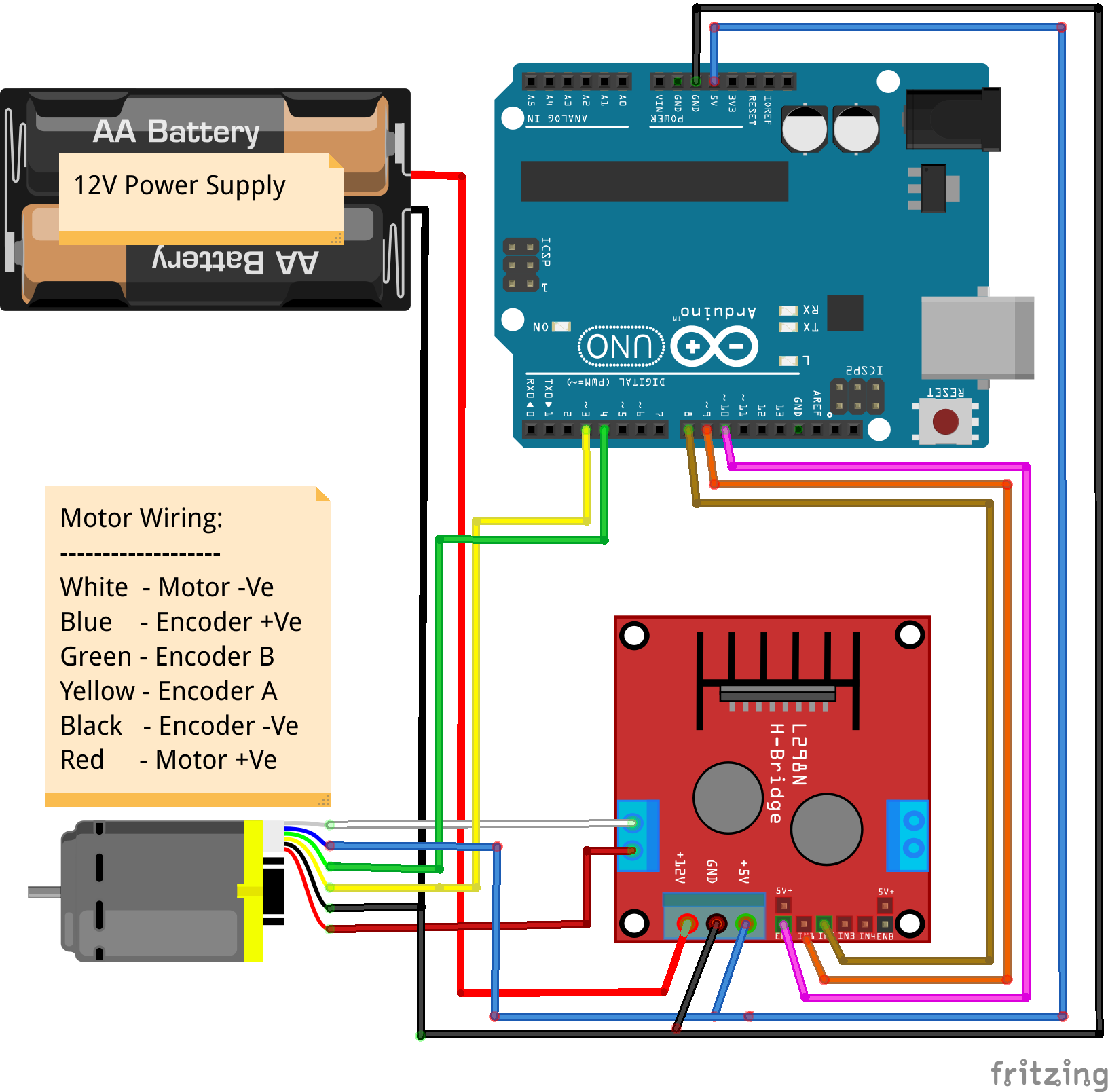
I hope understanding the circuit is pretty straight forward. We just need to ensure that we have a common ground while the rest of the connections are self-explanatory. We just have connected a single motor to the circuit, though a single L298N H bridge can take 2 Motors. If we use the L298N H bridge in our Navo robot is a discussion for later as there are much better motor controllers which we will consider when we talk about the actual build.
Power Supply
As it can also be seen from the schematic above is that, we are using a 12V external power supply from a battery pack. This is just about enough to also power the Arduino board.
The Logic
We have already deduced how we could measure the RPM of the DC Motor that we are using. More information about the Arduino sketch can be found here. There is nothing ROS specific about that sketch. We will use that sketch as a starting point and make it respond to ROS messages from a ROS node, while at the same time, make that sketch send back messages to another ROS node with the RPM that the motor is currently running. Let's get our hands dirty!
Additionally, have a look here to understand how ROS works with the Arduino using ROS serial libraries. We use a PID control mechanism for doing the speed control, have a look here for a basic understanding of the PID controller.
TODO.... Sketch and further documentation